Optical models

 Planck constant and
  is photon frequency.
Coherent transfer matrix method
Transfer matrix method a convenient way of modeling thin film stacks. It is assumed that layers are
stacked along  axis, with
  being interface between layer
  and
layer
and
layer  . Optical properties of each layer are specified by wavelength dependent complex
refraction coefficient
. Optical properties of each layer are specified by wavelength dependent complex
refraction coefficient  .
.
Optical field inside layer at given point along axis is specified by column vector
![\left[E_{i}^{+}(x),E_{i}^{-}(x)\right]^T](_images/math/77d76ec819817938b244345e255fdb97d854b71b.png) , with
, with  being complex amplitude
of forward traveling wave, and
being complex amplitude
of forward traveling wave, and  being complex amplitude of backward traveling
wave.
being complex amplitude of backward traveling
wave.
Snell law is determines angles of propagation in each layer
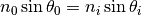
where index 0 refers to medium before first layer.  is angle of illuminating wave.
All angles can be complex numbers. Since
is angle of illuminating wave.
All angles can be complex numbers. Since  is multivalued function, angle of forward
traveling wave is found from conditions that forward wave has forward pointing Poynting vector,
or alternatively, that the amplitude of forward wave decays in absorbing medium.
is multivalued function, angle of forward
traveling wave is found from conditions that forward wave has forward pointing Poynting vector,
or alternatively, that the amplitude of forward wave decays in absorbing medium.
In this convention, interface between layers is described by matrix  as
as
![\left[\begin{array}{c}
E_{i}^{+}(x)\\
E_{i}^{-}(x)
\end{array}\right]=\mathbf{M_{i,i+1}}\left[\begin{array}{c}
E_{i+1}^{+}(x)\\
E_{i+1}^{-}(x)
\end{array}\right]](_images/math/92972c436f05fa895380e129042777ed32943897.png)
with entries of matrix specified as
![\mathbf{M_{i,i+1}}=\frac{1}{t_{i,i+1}}\left[\begin{array}{cc}
1 & r_{i,i+1}\\
r_{i,i+1} & 1
\end{array}\right]](_images/math/9cc7315987eea08bf1bea74a1f44bb32a8c3771f.png)
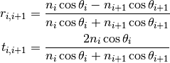
where transmission coefficient  and reflection coefficient
  are given by Fresnel equations for complex amplitudes of light passing from layer i to layer i+1. Coefficients for backward propagating wave
  and
and  are eliminated using Stokes relations.
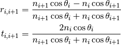
For s-polarized wave:
For p-polarized wave:
Propagation inside layer is described by matrix  as
as
![\left[\begin{array}{c}
E_{i}^{+}(x)\\
E_{i}^{-}(x)
\end{array}\right]=\mathbf{P_{i}(x)}\left[\begin{array}{c}
E_{i}^{+}(x=x_{i,i+1})\\
E_{i}^{-}(x=x_{i,i+1})
\end{array}\right]](_images/math/691baf63566a1c7aff2f0c61b7e600bc426f96c1.png)
![\mathbf{P_{i}(x)}=\left[\begin{array}{cc}
\exp-i\delta_{i}(x) & 0\\
0 & \exp i\delta_{i}(x)
\end{array}\right]](_images/math/f0d992b455edcd73ca00091d1521e8abbfab695a.png)
with phase-shift
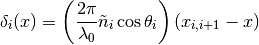
Light entering layer , on side of layer  has vector of complex amplitudes
![\mathbf{v_k} \left( x=x_{k-1,k} \right) =\left(\Pi_{k\le i\le n}\mathbf{M_{i-1,i}}\mathbf{P_{i}}(x_{i-1,i})\right)\mathbf{M_{n,n+1}}\left[\begin{array}{c}
t\\
0
\end{array}\right]](_images/math/89f5b98a76f017f13a053c048e5177e9d1a3586d.png)
with vector ![\left[t,0\right]](_images/math/003de84277dda5b60d070eb7250af961aa77d473.png) denoting light leaving the device on the side opposite to illumination, with
denoting light leaving the device on the side opposite to illumination, with  being complex amplitude of transmitted wave.
Applying above to whole device gives
![\left[\begin{array}{c}
1\\
r
\end{array}\right] = \mathbf{v_1}](_images/math/14b31c50d66b37d688c2c18a8fa049fb41e40921.png)
with amplitude of illuminating wave set arbitrarily to  and
and  being complex amplitude of reflected wave.
When analyzing stack, firstly, solution , is found. Then intensity of light anywhere inside the device is calculated using found vectors  and propagation matrices
  . Total intensity is found by applying Poynting formula. Absorbed energy is found by differentiating with respect to .
Incoherent light
Incoherent light is described by spectrum  . Absorption of incoherent light is calculated as
where  is calculated using coherent transfer matrix method.